
Installation and Connection of a Manifold
Why correct manifold installation matters so much
The manifold is the node through which the entire output of a zone's underfloor heating passes. It's not just a "junction" - it's the point where flow to individual circuits is regulated, where temperature is measured (on models with thermostatic heads directly on the manifold), and where, in the event of a fault, a circuit can be shut off without draining the whole system. If installation is done incorrectly, it usually shows up only after several weeks or months of operation - not right at first startup.
Typical consequences of poor installation: uneven heating between rooms (one circuit is "starved", another gets too much flow), bubbling and noise in the pipework caused by air that never got out through the bleed valve, dripping from threaded joints after several months of temperature cycling, or a completely non-functional zone because the electrothermic actuator was wired to the wrong circuit. The extra time spent during installation - checking tightness, following the right order of steps, a thorough pressure test - always pays for itself in fewer service calls once everything is built into the floor, where any intervention is many times more expensive.
What you'll need before installation
Before you start, get everything ready at once - a manifold is best installed in one uninterrupted sequence of steps, without unnecessary pauses due to a missing part:
- The stainless steel manifold itself with the correct number of circuits (2-, 3- or 4-way, or more according to the design).
- Manifold brackets/holders - usually included in the package, used to anchor it in the cabinet or on the wall.
- Ball shut-off valves or a valve group on both the flow and return pipework ahead of the manifold - these let you shut off the whole manifold without touching the rest of the system.
- A mechanical debris filter ahead of the manifold inlet - in practice one of the most frequently skipped components, yet a cheap safeguard against clogged flow meters.
- Electrothermic actuators (if circuits are controlled by room thermostats) - typically 230 V or 24 V depending on the type of control.
- A manifold cabinet, recessed or wall-mounted, large enough for service access (allow at least 8-10 cm of free space in front of the manifold for installation and later maintenance).
- Tools: a torque wrench or an ordinary adjustable wrench, PTFE tape or hemp thread sealant, a pressure gauge, and a manual or electric pressure pump for the tightness test.
- The underfloor heating design/calculation - circuit lengths and their layout, so you know which circuit goes on which manifold branch.
If you're not sure how many circuits you'll need, we've dedicated a separate article to this topic - see How many manifold circuits do I need. The rule of thumb is that a single circuit shouldn't exceed roughly 100-120 m of pipe length (for commonly used 16 mm pipe), otherwise the pressure loss grows so much that the circulation pump can no longer provide enough flow.
Installation procedure step by step
The following procedure applies to a typical stainless steel manifold installation in a flat or house, where the heat source is a condensing boiler or heat pump and the manifold is housed in a recessed or wall-mounted cabinet:
- Fitting and anchoring the cabinet. The cabinet is anchored to the wall or recessed into a partition before the rough plastering. The height of the manifold's bottom edge above the finished floor level should leave enough room to connect the circuits from below without bending the pipe below its minimum bend radius.
- Anchoring the manifold to the brackets. The manifold is fitted onto the supplied brackets in a horizontal position - the heating (flow) branch is usually at the bottom, the return at the top, or the other way round depending on the specific model; always check the orientation in the manual, since swapping sides complicates flow measurement later.
- Connecting the shut-off valves and filter. Ball shut-off valves are fitted first at the manifold inlet (on both branches - flow and return), with a mechanical debris filter ahead of the flow. This is the step most often skipped to save money - but in practice, without shut-off valves the manifold can never be taken offline for servicing without draining the whole branch.
- Connecting the supply pipework from the heat source. The flow and return from the boiler/heat pump (or from a mixing station, if the zone is weather-compensated) are connected to the shut-off valves. Use PTFE tape or hemp sealant here - never force the tightening, the thread in the stainless material can be damaged fairly easily.
- Connecting the individual underfloor heating circuits. Each circuit (flow and return) is connected to its own manifold branch via compression fittings. It's a good idea to write down or label right away which circuit leads to which room - this makes later flow adjustment and any servicing much easier.
- Electrical wiring of actuators and controls (if part of the design) - a detailed procedure is in a separate section below.
- Bleeding and initial filling - the manifold has its own bleed valves on both branches, which are opened while filling the system, until water flows out free of air bubbles.
- Pressure tightness test - always carried out before the floor is poured, details below.
You can also picture this procedure graphically - the diagram below summarises the eight steps in the order they should follow one another:
Wiring electrothermic actuators and controls
If individual circuits or zones are controlled by room thermostats, an electrothermic actuator is fitted onto the manifold for each circuit (or group of circuits in one room). It acts as an electrically operated shut-off valve - when the room thermostat sends a "heat" signal, the actuator opens (for common normally-closed actuators, voltage is applied and the spindle opens the flow); once the thermostat reaches the target temperature, voltage is removed and the actuator closes after a few minutes.
In practice we see two types of power supply:
- 230 V actuators - powered directly from mains voltage via a relay in the control unit, common in both older and newer installations, simpler to wire but requiring greater care when working under live voltage.
- 24 V actuators - powered by safe low voltage from a transformer in the control unit, safer to install and service, increasingly the choice today especially combined with smart controls and wireless room thermostats.
The actuator type must match the type of control unit - a 230 V actuator must never be connected to a 24 V control output and vice versa; mechanically the actuator always screws onto the manifold the same way, but electrically, with the wrong voltage, it either doesn't work at all or, if a higher voltage is applied to a low-voltage output, it can damage the control unit.
A simplified diagram of the signal chain looks like this: the room thermostat evaluates the temperature and, when it drops below the set value, sends a signal to the control unit (wired or wireless); the control unit then applies voltage, via a relay or directly, to the specific electrothermic actuator on the manifold; the actuator opens and releases flow into the corresponding circuit:
When choosing actuators for a typical flat or house, you'll most often come across these two versions:
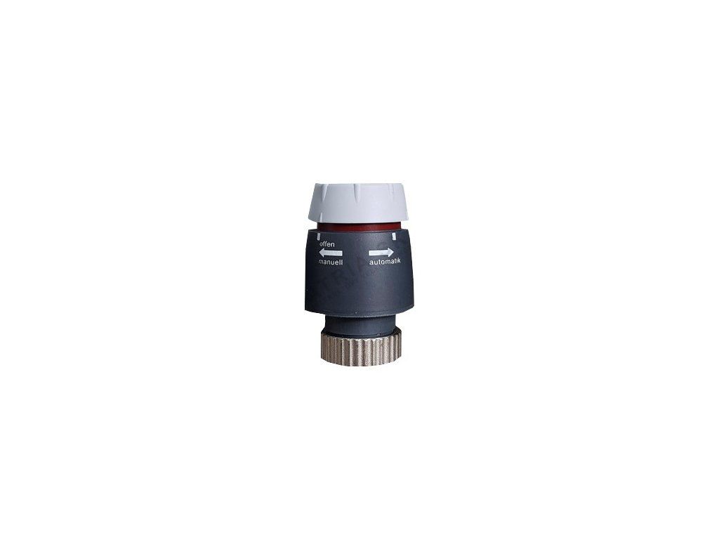 |
Electrothermic actuator 230 V - suitable for installations where the control unit and room thermostats work directly on mains voltage, simple wiring without a transformer. Price from €16.36. |
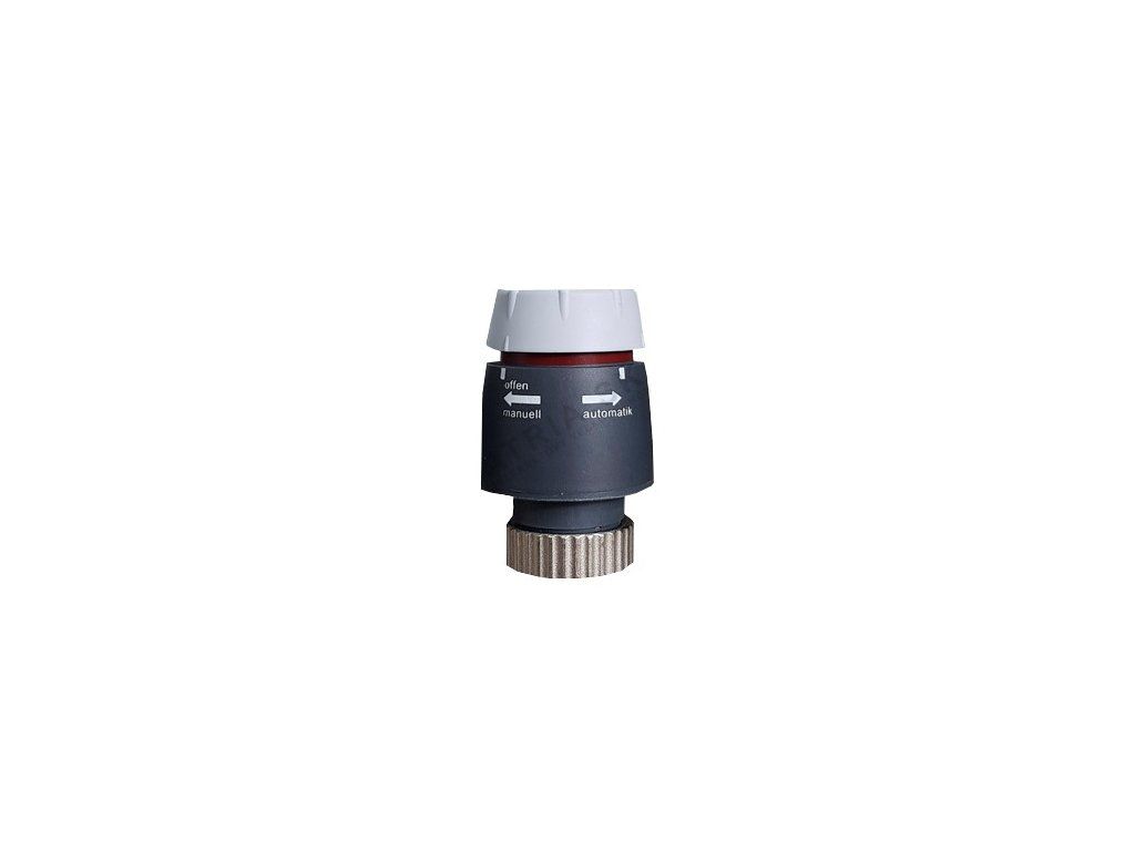 |
Electrothermic actuator 24 V - a safer choice for installations with low-voltage control, commonly combined with wireless room thermostats. Price from €16.36. |
Both actuators cost the same, €16.36 - the difference is purely in the type of power supply, so choose based on the control unit you already have or plan to use, not the price.
Choosing a manifold by number of circuits
The number of ways (circuits) on a manifold follows from the underfloor heating design - how many separate pipe loops run from the manifold into the floor. A typical flat with 2-3 rooms is fine with a 2- or 3-way manifold, while a larger flat or smaller house usually needs 4 or more ways. In our range you'll find these stainless steel manifolds:
 |
2-way stainless steel manifold for underfloor heating - suitable for a smaller zone, for example a bathroom and hallway, or one larger room split into two loops. Price from €53.68. |
 |
3-way stainless steel manifold for underfloor heating - a good choice for a smaller flat (living room, kitchen, one bedroom) or for extending an existing zone. Price from €69.39. |
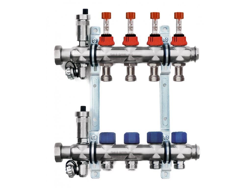 |
4-way stainless steel manifold for underfloor heating - a typical choice for an average house or larger flat with several independently controlled rooms. Price from €85.32. |
As you can see, price rises by roughly €15-16 for each additional way (€53.68 → €69.39 → €85.32), matching the cost of an extra pair of flow and shut-off valves on the longer manifold body. The chart below shows this more clearly:
When deciding between a larger manifold with a margin and one sized exactly to the current design, we always recommend choosing at least one way more than the current design shows - a future renovation or extension can then be connected without replacing the whole manifold. For a more detailed comparison with brass variants, see the article Stainless steel vs. brass manifold.
The most common installation mistakes
From real service calls and customer questions, we know that a few specific mistakes keep recurring:
A missing mechanical debris filter
Without a filter, small metal shavings or pipe deposits eventually reach the flow meters and valve seats, a flow meter gets stuck in one position, and the circuit stops responding to its setting. A filter costs only a fraction of the manifold's price, but replacing or cleaning it once it's built into the floor is far more expensive.
Missing shut-off valves ahead of the manifold
Without them, any service job (replacing an actuator, cleaning the filter) requires draining the whole heating system, not just that zone. The cost of a pair of ball valves is negligible compared to the time and water they save on future servicing.
Incorrectly connecting the flow and return
If the flow and return branches are swapped, the system usually still works, but flow readings and the behaviour of thermostatic elements (if fitted on the manifold) can be inaccurate. Always check the orientation in the manual for your specific model.
Mixing up actuator voltage (230 V vs. 24 V)
As described above, this is one of the most costly mistakes - the wrong voltage can damage the control unit. Always check what type of output your control system has before buying actuators.
Skipping or rushing the pressure test
The tightness test is sometimes skipped under pressure to meet a deadline for pouring the floor screed. If a leak appears after pouring, the fix means breaking up a finished floor - completely incomparable, in cost and time, to a few extra dozen minutes before pouring.
Insufficient service space in the cabinet
A manifold fitted too tightly into a small cabinet can't be properly bled or serviced later - actuators can't be replaced without removing the whole cabinet. Allow for sufficient cabinet depth already at the design stage.
Missing circuit labelling
Without labels or a note showing which circuit leads to which room, any future flow adjustment or fault-finding takes needlessly long. Labelling takes just a few minutes right during installation.
For a more detailed overview of typical faults and how to recognise them, we recommend the article Most common manifold faults.
Pressure tightness test before pouring the floor
The pressure test is the last and most important step before the circuits are covered with a concrete or anhydrite screed. The principle is simple: fill the system with water, bleed it, then pressurise it to a value significantly higher than the normal operating pressure, and observe whether the pressure drops over a set period.
In practice, the usual approach is: the operating pressure of underfloor heating in flats and houses typically runs around 1.5-2.5 bar. The test pressure is set to roughly double this value, i.e. around 4-6 bar (always within the limits of the maximum operating pressure of the pipe and manifold according to the manufacturer's data sheet). Pressure is held for at least 30 minutes for a short, rough check, but before the final pour a longer test - 24 hours - is recommended, so that even small leaks that wouldn't show up as a pressure drop within the first half hour have time to reveal themselves.
The overview below summarises both types of test side by side:
Throughout the whole test (especially the long, 24-hour one), we recommend recording the pressure and room air temperature - a pressure drop caused purely by a temperature change (water cooling in the pipes) can be distinguished from a genuine leak by comparing it with the temperature. If pressure drops noticeably faster than temperature contraction would explain, all joints need to be systematically checked - first on the manifold itself (compression fittings, shut-off valve threads), then the crossings through the floor, and finally the joints at the heat source.
Only after a successful pressure test (and documenting it - a photo of the gauge with a date is a common and cheap way to have proof in case of a future complaint) is it appropriate to pour the screed over the circuits. The system is kept under mild pressure (not necessarily the full test pressure) during pouring and drying of the screed, so that any mechanical damage to the pipe during pouring shows up immediately as a pressure drop, not years later.
Commissioning and balancing the circuits
After the screed has dried and heating is switched on for the first time, the flow on individual circuits needs to be balanced - without this, one room can be overheated and another underheated, even if the manifold and actuators were installed perfectly correctly. Balancing is done using the flow meters directly on the manifold (usually built into the body on one of the branches) - based on the designed length and output of each circuit, an approximate flow in litres per minute is set on each circuit individually.
In practice, it's common that even after the initial setting based on the design, flows need to be fine-tuned empirically - i.e. based on how warm each room actually feels during the first heating period. Rooms with larger glazed areas or a north-facing orientation usually need somewhat higher flow, while bathrooms with a short circuit need lower flow so they don't overheat. This process typically takes one to two heating seasons before the ideal setting for a given house is found.
If the controls include room thermostats and electrothermic actuators, it's also worth verifying that each thermostat really does control the actuator on the correct circuit - the simplest test is to disconnect/connect voltage on individual actuators one at a time and watch which flow meter on the manifold reacts. It's worth doing this right after commissioning, while access to the manifold is still convenient and any mistake can be fixed without major work.
For more comprehensive control of several zones at once, it's also worth considering a central control panel or a simple switching module - for example:
 |
Avansa 2003 - a suitable addition for more extensive control of several underfloor heating zones together with the manifold. Price from €20.05. |
Regular checks after installation
Even a correctly installed manifold needs a minimum of regular care - once a year (typically before the heating season starts), check that the shut-off valves move freely (not seized), that the bleed valves aren't leaking, and that the mechanical debris filter isn't clogged. You'll find a detailed maintenance procedure and everything worth checking in the article Maintenance of a stainless steel manifold. When choosing a suitable cabinet with enough room for these regular checks, we also recommend the article Manifold cabinets - what size.
Frequently asked questions
Does a manifold always need to be horizontal?
Yes, stainless steel manifolds for underfloor heating are designed for horizontal installation - a vertical or tilted position can affect bleeding accuracy as well as the function of the flow meters, which rely on any bubbles settling upward under gravity.
Can a manifold be added later, once the floor is already finished?
The manifold itself, yes, as long as it's accessible in a cabinet or on a wall outside the floor - the problem only arises if you need to add an entirely new circuit routed through the floor, which can't be done without redoing the surface. If it's just a replacement or extension using existing connections, that's a routine service job.
How many circuits can I connect to one 4-way manifold?
Exactly four separate circuits - the number of ways in the manifold's name matches the number of pipe loops that can be connected. If you're planning more circuits, you'll need a manifold with more ways, or to add a second manifold alongside it.
Do I need to use PTFE tape, or is tightening the thread enough?
PTFE tape or hemp sealant is always recommended on threaded joints (for example between a shut-off valve and the pipework) - metal-on-metal tightening alone, without a seal, eventually starts leaking as temperatures cycle. Compression fittings on the pipes to the circuits have their own seal (an O-ring), and PTFE isn't used there.
How long can a manifold stay under pressure before the screed is poured?
The recommended long test lasts at least 24 hours, but common practice is to leave the system under mild pressure throughout the actual pouring and drying of the screed (usually several days to weeks) - this way any mechanical damage is revealed immediately, not only after the floor is later uncovered.
Can I combine 230 V and 24 V actuators on one manifold?
Mechanically, yes, since they screw onto every manifold valve the same way, but electrically, no - each actuator has to be powered from the matching output of its control unit. In practice this means you can only have both types on one manifold if you also have two separate control units with the matching voltage, which is rare in a typical installation and not recommended, for the sake of simpler servicing.
What should I do if, after filling, one circuit doesn't pass any water at all?
First check that the shut-off or thermostatic valve on that circuit is fully open and that the actuator (if fitted) is receiving voltage. If everything is open and flow is still missing, it could be an air pocket in that circuit - a more thorough bleed of that specific branch, at a slightly higher pressure, usually helps.
Related topics
- How to choose a stainless steel manifold
- How many manifold circuits do I need
- Stainless steel vs. brass manifold
- Bleeding and setting up a manifold
- Most common manifold faults
- Maintenance of a stainless steel manifold
- Stainless steel manifolds
Do you have a question on this topic?
Can't decide, or dealing with a specific situation in your home? Write to us - we're happy to help.