
Installing a Resistance Cable
Installing a resistance cable - a practical step-by-step guide
A resistance heating cable is one of those technologies that looks simple on paper - you lay the cable, plug it in or connect it to the distribution board, and you're done. In practice, though, there's a difference between an installation that works trouble-free for ten years or more, and one that shows up after the first winter as a burst pipe, burnt insulation, or a tripping circuit breaker. This article sums up what usually only gets addressed once the cable is already embedded in the floor or under the gutter - in other words, before you start the actual installation.
We draw on common situations we come across selling resistance cables for three main areas of use: protecting pipes against freezing, gutters and roofs against ice and snow, and, to a lesser extent, floor heating. Each of these applications has its own specifics, but the installation procedure shares a common core - and that's what this article covers.
When correct installation matters most
A resistance cable works on a simple principle - electric current passing through a resistance conductor is converted into heat. With a classic resistance cable, the amount of heat per metre of length (measured in W/m) is practically constant throughout operation, regardless of whether the cable is out in the open air or wrapped in insulation. This is a key difference from self-regulating cables, which adjust their output according to the ambient temperature - and that's exactly why it's more important to keep the correct spacing and lengths with classic resistance cables, since the cable "doesn't know" how to protect itself from overheating over a short section.
If the cable crosses over itself at one point, or is coiled tightly into a small area, the heat there has nowhere to go. The result can be local overheating, degradation of the cable's insulation, and, in the worst case, a fire risk. This is the most common cause of complaints we come across - not a fault in the cable itself, but the wrong way of laying it.
Types of installation by intended use
Before getting into the procedure itself, it's important to establish which application you're dealing with, since both the fixing method and the required output per metre differ.
Installation on a pipe (frost protection)
The most common use - water pipes, connections to the house, pipes in outdoor shafts or unheated spaces (a garage, utility room, attic). A typical output is 10 to 20 W per running metre of pipe, higher for larger diameters or more extreme climate conditions. We cover choosing the cable by pipe diameter and climate zone in detail in a separate article, How to choose a heating resistance cable.
Installation on a roof and in gutters
This is a different task - not keeping a pipe above freezing, but melting ice and snow in gutters and downpipes, where ice dams and backed-up water under the roof covering would otherwise form. Both the output and the way the cable is laid (loops in the gutter, a zigzag on the roof) are completely different from pipe installation. We cover this topic in detail in the article Resistance cable for roofs and gutters against ice, so here we only give the basic principles it shares with pipe installation.
Floor heating and de-icing outdoor surfaces
A resistance cable is also used as supplementary or main floor heating, or for de-icing outdoor steps, ramps and paths. Here the cable is laid across a continuous area with a precisely defined loop spacing, which, from an installation point of view, is a completely different discipline from coiling it round a pipe. You'll find a comparison with classic heating mats in the article Resistance cable vs. heating mats.
The rest of this article focuses mainly on pipe installation, since it's the most common case we come across with orders - however, the principles of electrical connection, protection and post-installation checks are the same for all three applications.
What you'll need before starting installation
Before unpacking the cable, prepare:
- The resistance cable itself, in a sufficient length (always allow a 0.5-1 m margin extra for the connector and termination - the cable can't be shortened on site).
- Self-adhesive aluminium tape - used to fix the cable to the pipe at regular intervals and also helps distribute heat evenly across the pipe's surface.
- Thermal insulation (sleeve or strip type) - the cable is always installed under the pipe insulation, never left bare without insulation, otherwise most of the heat produced is lost to the surrounding air instead of the pipe.
- A soldered or heat-shrink end/connector kit (termination and connector set) supplied with the cable, or compatible with that type of cable.
- A residual current device (RCD) with a 30 mA tripping current - for damp areas and outdoor applications, this is the most important item on the list, not an optional extra.
- A thermostat or controller (if not supplied with the cable) - without one, the cable runs continuously, needlessly increasing consumption.
- An insulation resistance tester (megohmmeter) to check the cable both before and after installation - a more expensive item, but worth borrowing, since it catches a fault before you insulate and bury the pipe.
- Standard electrician's tools - screwdriver, pliers, a torque driver for the distribution board terminals.
Step-by-step installation procedure
The diagram below sums up six steps we recommend following in this order. Skipping the check measurement before insulating is the most common mistake, and it comes back to bite you expensively later, since any fault in the cable can no longer be easily fixed once it's been insulated and buried without digging it back up.
Straight installation vs. spiral winding on a pipe
For smaller-diameter pipes (usually up to roughly 40-50 mm), the cable runs straight along the length of the pipe, or with one or two strips side by side for a larger diameter. For larger pipe diameters (above 50 mm), a single straight strip of cable can no longer distribute evenly around the whole circumference, so the cable is wound in a spiral. The larger the pipe diameter, the tighter the winding needs to be to achieve the same equivalent output per metre of pipe length.
Typical rough figures used when designing this (they vary by the specific cable type and climate zone, and you should always work from the specific product's technical sheet):
- Pipe up to DN20 (roughly up to 20-25 mm) - a single straight strip of cable is enough at a typical outdoor temperature.
- Pipe DN25 - DN50 - a single straight strip, or two parallel strips depending on insulation thickness and climate zone.
- Pipe above DN50 - spiral winding with a pitch matched to the required output per metre of pipe.
The diagram below illustrates the principle - as the pipe diameter increases, the length of cable used for the same section of pipe has to increase proportionally to maintain the required output per unit of surface area.
The exact figures for a specific diameter and pipe type can always be found in the technical sheet of the specific cable - the figures above are only approximate, to illustrate the principle of why the cable length per metre of pipe increases with a growing diameter.
When winding a spiral, it's important to keep to the cable's minimum bend radius, which manufacturers usually state as roughly five times the cable's diameter. For a typical resistance cable diameter of around 6-8 mm, this means a minimum bend radius of roughly 30-40 mm - the cable must never be bent into a sharp angle, since this damages both the inner conductor and the insulation, creating locally increased stress at the bend.
Installation on a roof and in gutters - briefly
For gutter installation, the cable runs in regular loops along the bottom of the gutter and then continues into the downpipe, where it often forms a double loop right down to the outlet, to prevent freezing exactly where the water leaves the house's roof. On the roof itself, the cable runs in a zigzag pattern in the zone where ice dams most often form - typically at the eaves edge and around a chimney or dormer. It's fixed with special roof clips or hooks made specifically for that type of covering, never improvised with tape or wire, which won't hold up under temperature changes and snow loads. You'll find a detailed procedure, including recommended laying patterns, in the separate article Resistance cable for roofs and gutters against ice.
Electrical connection, protection and circuit sizing
This is the part of the installation where corners are most often cut in the wrong place - and exactly where most of the safety risks arise. A few principles that should apply without exception:
- A resistance cable must always be connected via a dedicated residual current device (RCD) with a 30 mA tripping current. For outdoor applications (roof, gutters, outdoor pipework), this is a necessity, not a recommendation - the cable is exposed to moisture, rain and mechanical stress over the long term.
- The cross-section of the supply cable and the protection (circuit breaker) must be chosen based on the heating cable's actual power draw, not by guesswork. At 230 V, a simple relationship applies: I = P / U, i.e. current in amps equals output in watts divided by voltage.
- When planning the circuit, you need to account for the total sum of all appliances on that circuit, not just the heating cable itself - a common mistake is connecting the cable to a circuit where another, larger appliance is already running, so that when both run at the same time, the breaker trips.
Example circuit load calculation
Let's take a common case - a heating cable with a total power draw of, say, 750 W (typically 50 m of cable at 15 W/m for pipe protection) represents a current of roughly 3.3 A at 230 V, which is only a small load compared with a typical 16 A breaker. The problem arises when another, larger appliance is connected to the same circuit - a typical example is a small storage water heater, which is often installed in the same space (utility room, bathroom, pantry) at the same time as the heating cable.
If, for example, you're also planning to replace or add a small storage water heater alongside installing the resistance cable, it's worth calculating in advance how much load it adds to the circuit. Here's a rough overview for three common power ratings:
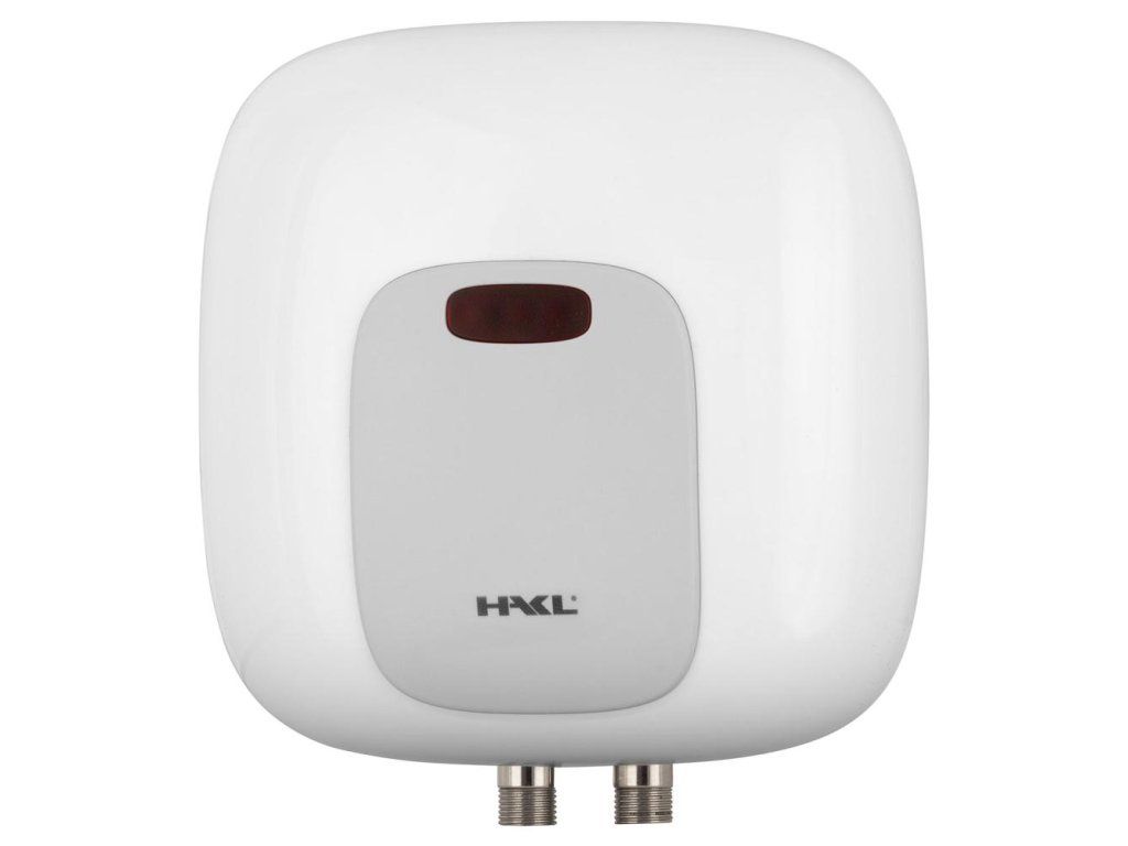 |
HAKL PL 3.5kW water heater - at a 3.5 kW power draw, this represents a load of roughly 15.2 A at 230 V, which just barely fits on a typical 16 A breaker, and combined with the heating cable would already overload the circuit. If you're planning both appliances on the same circuit, allow for this in advance. Price from EUR 95.94. |
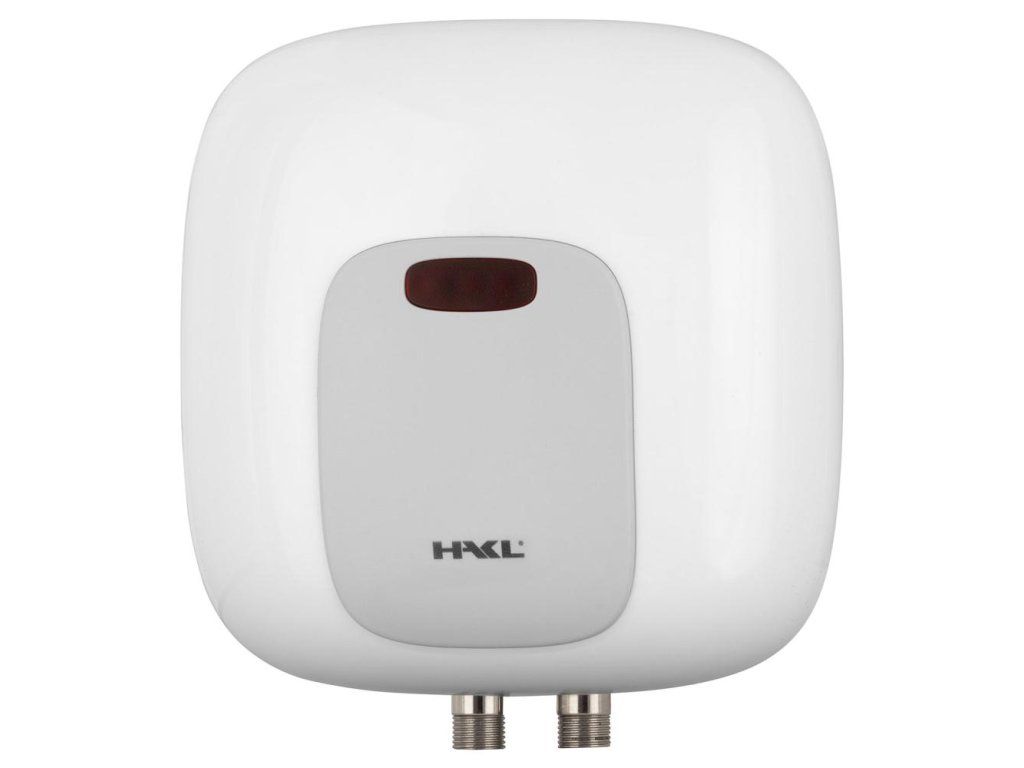 |
HAKL PL 4.5kW water heater - at a 4.5 kW power draw, that's already roughly 19.6 A, so this variant needs its own dedicated circuit with at least a 20 A breaker and should never be combined on the same 16 A circuit as the heating cable. Price from EUR 95.94. |
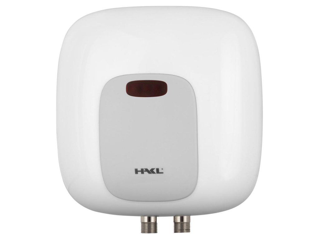 |
HAKL PL 5.5kW water heater - at 5.5 kW, the load is roughly 23.9 A, which requires a dedicated circuit with a higher-rated breaker (usually 25 A) and a suitably sized supply cable. This is a typical example of an appliance that has to be treated as a completely separate electrical circuit, independent of the heating cable. Price from EUR 95.94. |
The chart below sums up the three examples above together with the calculation for the heating cable itself, so you can clearly see how much extra load an appliance that looks small at first glance adds to the circuit compared with the resistance cable alone.
The chart shows why a heating cable for pipe protection can safely be connected to a circuit with a 16 A breaker, while any of the water heaters listed above already represents a significantly higher load that requires recalculating when combined with another appliance. Always leave the exact circuit sizing to a qualified electrician - this chart is only meant to give a rough sense of the order of magnitude, not to replace an electrical design.
Wiring diagram with a thermostat
A typical resistance cable wiring diagram looks like this - power runs from the distribution board through a 30 mA RCD to the thermostat (or a simple switching relay with a temperature sensor), from there to the connector/termination kit, and finally to the heating cable itself. The thermostat's temperature sensor is placed at the coldest point on the route (for example on the north side of a pipe, or the spot most exposed to wind), so the control matches the most critical point, not the average of the whole route.
The most common installation mistakes
From regular complaints and customer questions, these mistakes keep coming up:
- Cable without pipe insulation. The cable is wound directly onto the pipe, but the pipe is left uninsulated - most of the heat escapes into the air instead of the pipe, the cable runs almost continuously, and consumption is needlessly high.
- The cable crossing over itself. The cable crosses itself twice at one point, or is wound tightly side by side - this creates local overheating and a risk of insulation damage.
- Shortening the cable on site. A classic resistance cable (unlike some self-regulating types) can't simply be shortened on site without affecting the resistance conductor - order the exact length in advance, not "with a margin to cut off".
- Missing residual current device. For outdoor or damp applications, omitting the 30 mA RCD is a clear safety risk, not just a formality.
- Placing the thermostat sensor in an unsuitable spot. A sensor fixed on the sunny/south side of the pipe, or on a warmer part of the route, will cause the thermostat to switch the heating off before the coldest point on the route actually freezes.
- Skipping the check measurement before insulating. As mentioned above, this is the only moment when a fault can be fixed without dismantling finished insulation.
- Too sharp a bend in the cable. Especially when going round elbows and T-pieces in the pipework, the cable is often bent to a smaller radius than the manufacturer's minimum.
You'll find a more detailed overview of faults, including how to recognise that damage has already occurred, in the article The most common resistance cable faults.
Verification after installation - measuring insulation resistance
Once the electrical connection is complete, but before insulating the pipe, it's a good idea to carry out two checks:
- Measuring insulation resistance between the cable conductor and its protective braid/sheath using an insulation tester (megohmmeter). The exact required value varies by manufacturer and cable type - always work from the specific product's technical sheet and compare the value with the one measured before installation (it should stay in a similar range; a significant drop signals damage during installation).
- Functional test - connecting the cable to power with the thermostat switched on and checking that the cable actually heats up (most simply by touch after a few minutes of operation, carefully, since the cable may be hot) and that the thermostat switches correctly when a temperature drop is simulated (for example by holding ice against the sensor).
We recommend recording both measurements (for example a photo of the measuring instrument's display) and keeping them together with the proof of purchase - in the event of a future warranty claim, this is valuable evidence that the cable was working and correctly connected at the time of installation.
Safety warnings
We always recommend leaving the electrical connection of a heating cable to someone with an electrical qualification or licence, especially the part from the distribution board to the connector kit. The mechanical part of laying the cable on the pipe (taping, winding) can be managed by a handy DIYer following the instructions in this article, but connecting it to the electrical system is an area where a mistake can mean a fire risk or electric shock. Never connect a resistance cable directly to a socket without an RCD and without a thermostat designed for that application - even if it "seems to work" at first glance, it's a solution that carries a long-term risk.
When working in damp spaces (shafts, outdoors), always switch off the relevant breaker in the distribution board before starting work and verify there's no voltage present with a tester - even if the equipment looks disconnected at first glance.
Frequently Asked Questions
Can a resistance cable be shortened if it's too long?
No, a classic resistance cable with a fixed resistance conductor can't be shortened on site without affecting the electrical properties of the whole cable. The length therefore needs to be worked out precisely in advance based on the actually measured length of the pipe or route, or you can order a cable with a slight margin, which during installation is simply dealt with by an extra loop, not by cutting.
Does the cable have to be under the pipe insulation, or is it enough on the surface?
The cable should always be laid under the pipe's thermal insulation. Without insulation, most of the heat produced is lost to the surrounding air instead of heating the pipe, the cable runs for longer, and electricity consumption is needlessly higher, while frost protection can still be inadequate during harder frosts.
Is a residual current device needed even if I'm only running the cable in a dry utility room?
We recommend a 30 mA RCD always, regardless of whether it's a damp outdoor location or a dry indoor one. The cable is subject to long-term temperature changes and mechanical stress during installation, so the risk of insulation damage over the years exists even in a dry environment.
How long does a resistance cable last with correct installation?
Following the correct installation procedure, correctly sizing the output, and using a quality thermostat, the typical service life runs to many years of operation. We cover the exact expected service life and the factors that shorten it the most in the article Maintenance and service life of resistance cables.
Can I fix the cable to a pipe with ordinary insulating tape instead of aluminium tape?
We don't recommend it. Aluminium tape not only mechanically holds the cable in place, it also helps distribute heat evenly across the pipe's surface, which ordinary insulating tape can't do, and it may also peel off or degrade faster at higher temperatures.
How do I know which thermostat or controller to choose for a given cable?
The specific type of control depends on the application (pipe vs. roof/gutters vs. floor) and on whether you want simple switching based on air temperature, or more precise control with a sensor right on the pipe. You'll find an overview of common control types and recommendations in the article Thermostats and control for resistance cables.
Related topics
- How to choose a heating resistance cable
- What cable output per m² do I need
- Resistance cable for roofs and gutters against ice
- Thermostats and control for resistance cables
- The most common resistance cable faults
You'll find the full range of resistance cables and accessories in the main category Resistance cables.
Have a question about installing a resistance cable?
Dealing with a specific case - a pipe diameter, a route length, or choosing the right thermostat? Write to us, we're happy to help with the choice and the installation procedure.